
|

|
1. PREFACE
The True History of the Telegraph
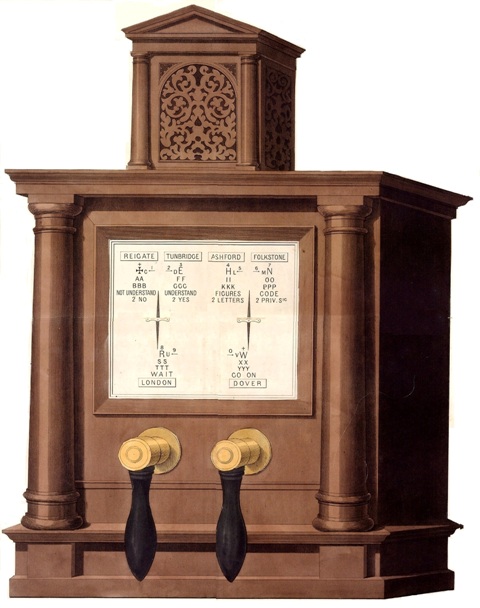 |
Cooke & Wheatstone’s two-needle telegraph 1842
"The Electric Telegraph"
Drawn and engraved by John Emslie, 10 Gray's Inn Terrace, London, and
Published by John Reynolds, 174 Strand, London, April 16, 1851
What is there to discover in Distant Writing?
Distant Writing is the history of all of the domestic public telegraph companies formed in Britain from 1838 to 1868, as well as of their associated cable companies. Starting from the earliest days of electrical technology, Distant Writing tries to put their remarkable, largely unrecognised, achievements and developments into the context of the time; and to demonstrate - surprisingly- how their enterprise is once again reflected in the way we communicate now. A plan for an electric telegraph in every home was just one of the schemes successfully introduced by the companies - until the Government took over...
Their working practices, employment policies, pricing structures, their influence on time and weather, and their relationships with the news media during the period are dealt with in some detail; as is the electrical technology that is inextricably and unavoidably linked to their development.
Readers will find a great many rare contemporary engravings of most of the instruments and many telegraphic features of the period throughout the text and in the Instrument Gallery.
It is hoped that all of this detail will encourage others to investigate and publish works regarding the electric telegraph in the nineteenth century; the innovation of which led directly to our electronic age.
Distant Writing first appeared on August 25, 2006 as part of the Atlantic Cable website; it graduated to its own web domain in April 2007. It was the very first and, surprisingly, is still the only work to give the history of the telegraph industry in Britain during the epic years between 1838 and 1868.
It was inspired, as long ago
as 1973, by the work of the late Jeffrey Kieve, whose pathfinding work
“The Electric Telegraph - A Social and Economic History” opened the
eyes of many to the commencement of our electronic age.
Questions and corrections are all welcome.
Periculum privatum utilitas publica!
Steven Roberts
In detail...
Distant Writing
is now
illustrated with over 450 original engravings from the period
between 1838 and 1870, as well as 4 large maps, 6 city plans,
small-scale maps for cable projects in the Atlantic, the telegraphs in
Europe, the Levant and the Far East, and early circuit diagrams, many
of which have been lost to view
for over a hundred years. There is a newly discovered, detailed coloured map of the telegraphs in Europe in 1856.
Introduction describing the state of personal communications before electric telegraphy; as well as -
Cooke & Wheatstone - A view of the creators of Britain’s telegraph, their initial slow progress introducing the electric telegraph, their first lines, the innovation electric railway signalling for safety, and their fraught relationship in the 1830s and 1840s.This chapter was revised in November 2010 to include important new research on their earliest intruments;
The Electric Telegraph Company - A comprehensive history of the first company formed to offer the public access to telegraphy. From when it was launched in 1846, its early crises and eventual domination in its domestic market, to its contribution to the success of the world-wide cable network after it had become the Electric & International Telegraph Company in 1855. Detailing for the first time its efforts to create a global communications network from London to Calcutta in the 1850s and 1860s, dating from the original scheme for a cross Channel cable in 1847 to planning, in 1863, its own system in British India, using its alliances with Prussia and Russia to connect London with Bombay and Calcutta. It anticipated reaching New York by telegraph overland by way of Siberia, Russian America, Canada and California. It even experimented with wireless telegraphy in 1863!
Competitors and Allies - The history of the many other organisations in telegraphy, including the British Electric Telegraph Company, the English & Irish Magnetic Telegraph Company, the European Telegraph Company, the Submarine Telegraph Company, the Electric Telegraph Company of Ireland, the Irish Sub-Marine Telegraph Company, the International Telegraph Company, the British & Irish Magnetic Telegraph Company, the London District Telegraph Company, the United Kingdom Electric Telegraph Company, Bonelli’s Electric Telegraph Company, the Economic Telegraph Company, Reuter’s Telegram Company, the Great Northern Telegraph Company, the Indo-European Telegraph Company and the many others that worked public telegraphs in Britain, whose stories have never before been told;
The Universal Telegraph
- The very first history of domestic and private telegraphy and
the revolutionary instrument perfected by Charles Wheatstone in 1858
which succeeded in networking individuals in the cities of Britain with
desk-top instruments and desk-top printers during the 1860s. It is the
curious and complex story of his Universal Private Telegraph Company,
and its competitors, as it ventured from private networks with
switch-boards and exchanges into public telegraphs, telemetry,
time transmission, exploders for mining and warfare, the
development of secret submarine weapons and the introduction of
the ‘unbreakable’ cipher machine, the Cryptograph, used by the
Queen’s household, the government, the police and the Emperor of the
French. It is the tale of the first “technology” company.
Revised in June 2012, this page also now includes the stories of other
concerns in the private telegraph business, especially, and for the
first time, the work of the London District Telegraph Company which
pioneered large-scale, closed private networks:
Bain - Revised and extended again in June 2012, this is the most comprehensive perspective on the achievements and disappointments of Alexander Bain in telegraphy during the 1840s, 1850s and 1860s, including the short-lived Electric Time Company, accompanied by many engravings of his early instruments;
Non-Competitors - A summary of the many individuals and unsuccessful firms involved in public telegraphy, optical and electrical, who tried and failed, including the first of all, the Voltaic Telegraph Company of 1838, as well as the Liverpool & Holyhead Telegraph, the General Telegraph Association, the Marine Telegraph Association, the Scottish Electric Telegraph Company, the General Oceanic Telegraph Company, the General Commercial Telegraph Company, the General Telegraph Company, the Universal Electric Telegraph Company, and the Globe Telegraph Company; describing, too, S F B Morse’s embarrassing attempt to enter the field in London during 1845;
How the Companies worked - The story in some detail of their relationship with the public, their marketing, their staff, systems and processes, including the introduction of “electric banking” in the 1860s, with new descriptions of the earliest telegraph codes, and additional personal memoirs and articles on telegraph working in Britain in the 1840s and 1850s;
What the Companies charged - An explanation of how their complex pricing evolved and eventually simplified, and their price fixing cartel of 1855;
The Companies and the News - The first and wholly original story of the initial electronic news-gathering organisation of 1848, created by the Electric Telegraph Company, its competitors, the enmity of the press to telegraphy and the arrival of Reuter;
The Companies and the Weather - The incidental story of how the telegraph enabled weather forecasting;
The Companies Abroad - A summary of how the domestic telegraph companies and the new cable companies eventually conquered the oceans, especially the route to India, and the East India Company's lines, with a brief comparison of how their stock market prices boomed in the 1860s;
The Companies’ Foreign Operations - An explanation of their overseas pricing and their technical problems, and how telegram agencies sought to undermine their pricing with all manner of tricks;
Railway Signal Telegraphy – A brief, illustrated history of the earliest innovations in electric train control between the years 1838 and 1868, including the very advanced apparatus of the Railway Electric Signals Company;
Telegraph at War - The story of the first field telegraph, designed by the Electric Telegraph Company for the campaign in the Crimea in 1854; the unique Crimea submarine cable connecting the front with London; and the subsequent use of the telegraph by the British Army and by other countries at war, including France, Spain and Prussia, until 1868;
Technical Detail - A mass of detail that attempts to explain the technology, public and private, used by each telegraph company between 1836 and 1868, and connected devices such as batteries, blasting machines, and burglar and fire alarms. There is also a description of the “air circuits”, the pneumatic tubes used in the Cities from 1854, as well as the “wireless telegraph” of 1862;
Finale
- In which the successes of the companies and the economic failures of
the government telegraphs are briefly analysed. Including stock
and share price comparisons for all the companies year by year between
1861 and 1868.
Telegraph Stations 1862 - A consolidated list of all 1,178 cities and towns in Britain with public telegraphs in a typical mid-century year
Telegraph Company Stamps - A short, illustrated history of all of the stamps and franks issued by the companies between 1854 and 1868
The Rest of the World - Cooke & Wheatstone and the Growth of the Telegraph in Europe, the Telegraph in the United States, and a Statistical Comparison of the World’s Telegraphs
Instrument Gallery - In addition to many pictures and engravings in the chapters there is a host of illustrations, taken from patents, catalogues, books and journals of the 1840s, 1850s, 1860s and 1870s, of most of the telegraphic instruments mentioned in the text
Telegraph Maps 1852-1868 - with a large coloured “Chart of the Electric Telegraph Company’s System in Great Britain” in 1852; the Electric company’s coloured “Map of the Telegraph Lines of Europe” for 1856; the slightly later “Telegraphs of Europe” of 1860 in black and white also published by the Electric & International Telegraph Company, with all of its continental connections just before the worldwide expansion of wires and cables; a smaller scale “Telegraph Map of the Eastern World” in 1865 from the ‘Illustrated London News’; and a newly-restored “System Map of the London District Telegraph Company” from 1866, all of these are downloadable in a large size. There are also a set of city diagrams from 1868 showing the location of the telegraph offices in Birmingham, Edinburgh, Glasgow, Leeds, Liverpool and Manchester
Appendices - Comprising a List of Telegraph Companies from 1838 to 1868; the Domestic Telegraph Companies in 1868; the Addresses and Locations of Companies; a List of Domestic and Foreign Cables; Biographies of Company Personalities, now fully revised and much extended to include lesser-known telegraphic characters; a List of Telegraphic Suppliers of the 1850s and 1860s; Special Acts of Parliament that authorised the companies; Royal Charters obtained by the companies; Government Acts affecting telegraphy; Significant Telegraphic Patents; the Legal Context; a Glossary of Nineteenth Century Telegraphic Terms; concluding with a little melodrama, “Electric Sparks”, set within an electric telegraph office...
The Most Wonderful Thing
“We went to the Exhibition and had the electric telegraph show explained and demonstrated before us. It is the most wonderful thing and the boy who works it does so with the greatest of ease and rapidity. Messages were sent out to Manchester, Edinburgh, &c., and answers received in a few seconds – truly marvellous!”
Victoria R July 9,1851
“I have found material on your site invaluable. It’s a wonderful resource. Thank you very much for creating and maintaining it.” - Susan W. Brenner, Professor of Law & Technology, University of Dayton School of Law
“I have been reading your web-pages with interest. I am sure that they meet the long felt requirement to get that part of communications history into what is a very readable and useful perspective.” - Dr Allan Green, Research Fellow, Porthcurno Telegraph Museum
“Happened upon ‘Distant Writing’ just now, and am impressed.” - John McVey, Professor, Monserrat College of Art, Massachusetts
“I’m just writing to extend my heartfelt gratitude to you for putting together this absolutely wonderful resource!” – Dr R J Noakes, lecturer in science and technology, University of Exeter“Your web site is delightful, congratulations” - Dr Jon Peddie, President, Jon Peddie Research, California
“I have been immensely impressed by your masterly ‘Distant Writing’ ” - Sir George White Bt., F.S.A., Keeper, The Clockmakers’ Museum, London
“Interesting new pieces of information” - Dr Neil Barton BA MA FCIS FCMA FCCA FSI ASIP, University College London
History, No Paywalls
Many thanks are due from the writer to Bill Burns of Atlantic Cable for his generous support and continuing advice in so many aspects of researching the history of telegraphy. All who are interested in electric telegraphy, especially in the entire world-wide network of submarine cables, are recommended to his excellent, authoritative and hugely compendious website:
Atlantic Cable
Several other pieces on early telegraphy by Steven Roberts, the writer of Distant Writing, can be easily accessed from the:Links, Download & Contact Page
The entire text of Distant Writing is available as a download
in PDF format for easier reading
A Nineteenth Century Site : December 4, 2012