
15. RAILWAY SIGNAL TELEGRAPHY 1838 – 1868
To complete a view of telegraphy in Britain between 1838 and 1868 it is necessary to review railway signal telegraphy, which was introduced and developed in Britain during the period. This technology, to be clear, was intended to manage railway traffic and to prevent accidents; and is quite different from messaging. It is inextricably linked with railway signalling where the driver of the locomotive is authorised or forbidden to proceed by substantial line-side optical signals. The commonest of these visual signals was the semaphore; flat wooden arms atop tall poles, hinged at one end to work up and down, devised by the engineer Charles Hutton-Gregory in 1841.
As Captain Mark Huish, General Manager of the London & North-Western Railway, was to write (rather elaborately, and with his customary awareness of economy) in March 1854: "If only one collision of a passenger train, with its sickening accompaniments of suffering, to say nothing of its heavy expense, were prevented by free use of the telegraph, the immunity would be cheaply attained, and the cost of the improvement be amply compensated."
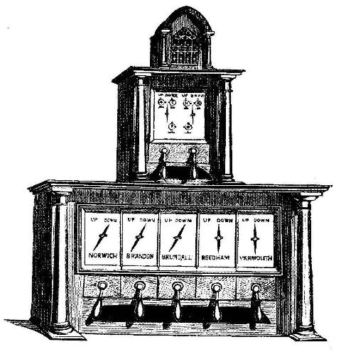
Cooke's Railway Signal Telegraph 1844
Every station could see the traffic on the whole line
The needles moved only momentarily and did not stay in the
left Up or right Down positions
There is a two-needle "speaking" telegraph and alarum above
The concept of "telegraphic railways" was proposed by W F Cooke in 1842. Railway signal telegraphy did not change in essence from Cooke's initial concept. In this each line of railway was divided into sections or "blocks" of several miles length. Entry to and exit from the block was to be authorised by electric telegraph and signalled by the line-side semaphore, so that only a single train could occupy the rails. Without electric telegraphy block signals could also be worked by a simple time-delay, allowing a period to elapse before the next train was permitted to enter. The catastrophic risks of this need not be elaborated.
Even in 1841 Cooke was keen to introduced automatic electric signalling, with "engine warners" inset into the railway track to indicate the passing of trains on the needle apparatus, as well as relying on railway police and signalmen to work the instruments. Unfortunately, he was never to achieve this.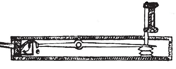
Cooke's patent "engine warner" 1841
A vertical rod protruded through the flanges of the rail, the
passage of a locomotive depressed it against an india-rubber cushion
to work a lever making a circuit, signalling to a needle telegraph
During the same year, 1841, Alexander
Bain patented a “railway controller”, connecting two locomotives electrically
by means of metal conductors set between the rails. If the first engine stopped
it automatically signalled the following one, should the signal be ignored a
bell was sounded, then as a last resort a weight was released to cut off the
steam, stopping the other train.
In the first form of railway signal telegraphy the company merely used the ordinary messaging instruments at its passenger stations, as there were then only external ground-frames with the levers that worked the semaphores, rather than enclosed signal-boxes, to send and receive abbreviated messages. This had great weaknesses in that the working of the telegraph was separate from the working of the signals, and in relying on the memory of the recipient as to the state of the rails ahead of and before any traffic, the message being momentary and not permanent.
a.] W F Cooke's Railway Signal Telegraph
In W F Cooke's original railway telegraph signalling system a
single-needle telegraph was adapted to indicate just two messages:
"Line Clear" and "Line Blocked". The signaller would adjust his
line-side semaphores accordingly. As first implemented in 1844 each
station had as many needles as there were stations on the line, giving
a complete picture of the traffic. This was far too elaborate, and a
sequence of single-needle instruments adopted, one pair for each
"block", working both directions of the railway. To be effective it
required the telegraph clerk to keep a record book to register all the
signals received. It was used in single pairs of instruments in several
locations throughout Britain as a "cheap and inefficient" solution for
well over ten years, until signal-boxes were generally introduced.
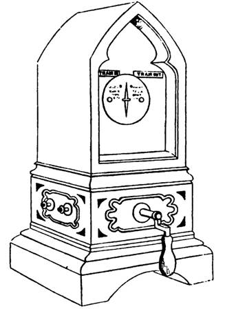
Cooke & Wheatstone's Railway Signal Telegraph 1850
As well as messages it signalled 'Train In' and 'Train Out' and
was used for something like a hundred years
In later years Cooke's single-needle block railway signal, with a record book or a writing slate for each section, was used in tandem in signal-boxes with a separate single-needle 'speaking' telegraph for railway messages, alongside of the levers for working the semaphore signals. This was to be, along with Highton's similar arrangement, the commonest train signalling system for over a century.
In addition to this the Electric Telegraph Company from its earliest days installed Wheatstone's magnet-and-bell, the earliest acoustic telegraph, line-side for railway signalling that worked without any batteries. In this a small magneto- electric machine, with twin coils and a lever-action, was in simple circuit with a distant electric bell to advise the signalman at the block semaphores by a series of beats. The Eastern Counties; Eastern Union; London & North-Western; Midland; South Staffordshire; York, Newcastle & Berwick; and York & North Midland all used the magnet-and-bell signal. The Eastern Counties possessed forty-nine and North-Western thirty-four out of a total of 114 magnets- and- bells in 1854; it was only applied to manage isolated sections, especially tunnels and single lines of way, on all of these railways. It was known from its impressive acoustic action as the "thunder pump". The last magnet- and- bell was apparently still in use on the Edinburgh & Glasgow Railway in the 1860s, where it had a code of fifteen different signals.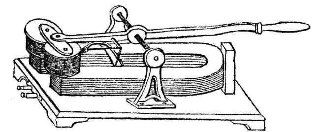
Pressing down the lever generated a pulse of electricity to ring a bell
b.] Edwin Clark's Railway Signal Telegraph
The Electric Telegraph Company's Edwin Clark devised improvements in
the signal system of the London & North-Western Railway in March
1854 with his proposals for a block system. He said:
"1st The machinery employed must be of the most simple and evident description, and not liable to derangement, and easily repaired.
"2nd The signals must be simple and few, and so distinctive that no mistakes can occur.
"3rd No dependence must be necessarily placed on the memory of the person in charge, and signals should be permanent and not temporary, or liable to misconstruction or neglect from the absence of the attendant.
"Lastly, and more particularly, no accident should be actually caused by derangement of the apparatus, or the absence of the signalman, but such absence or derangement should merely cause the delay of a train."
Clark's Railway Signal Telegraph 1854
Called the "two-mile" telegraph, as it policed two mile long sections
of railway tracks. Its continuous current allowed the
needles to give a permanent signal, left or right
Clark believed in, what would be called today, fail-safe operation and, unlike in the Electric company's public circuits, continuous currents to maintain a permanent reminder of the state of the block in front of the signalman. He used two Cooke & Wheatstone two-needle telegraphs, one for each line, up and down, in two-mile sections devoted entirely to signalling. A deflection to the left indicated train on line, a deflection to the right line clear, and no current meant line blocked, which was then to be considered a danger signal. The block instrument would normally show line clear, and would be changed to train on line when a train passed. When the train left the block, the instrument would signal back as line clear. In this system, unlike its single-needle predecessor, the signal was permanently displayed until changed by the operator. The drop handles could be locked in any position by means of a pin.An alarm bell was used to call attention of the signalmen. The telegraph wires were looped down certain poles, where they could be cut, so that the instruments then indicated line blocked and raised alarm. Each telegraph was worked in concert with a three-position semaphore signal on a tall post to visually communicate with the train crew at the commencement of the block.
The system was described in its earliest form in 'Civil Engineer & Architect's Journal' during 1857: "Among the more recent improvements adopted by the London and North-Western Company for securing perfect safety of travelling over their line, has been the establishment of a 'special train telegraph,' with signal stations every two miles. At each station a policeman is on duty night and day, in whose watch-box there is a telegraph dial with a single needle. By inclining the needle to the left hand, the person in charge gives notice to the next station that a train had passed on to the two miles of the road entrusted to his special care; while inclining it to the right hand would show that the train had passed off that portion of the line. There were in fact but two signals, 'train on' and 'train off,' but as it might happen that an accident occurred upon the two miles of road between the telegraph stations, the guard and breaks-man (sic) were instructed instantly to sever the 'special train wire,' which has the effect of placing the needle at each adjacent station in an upright position. The policeman on duty at once becomes aware by this movement that something is wrong, and can act according to circumstances."
Clark's so-called "Two-Mile Telegraph System" was installed in 1855 between Euston Square and Rugby, 83 miles, with signalling blocks actually 2½ miles in length. However there was no electrical signalling hence to Liverpool and Manchester at all, at this time. The instruments were controlled by the railway company's signalmen at both ends of the block, not by telegraph clerks. This had a counter defect in that there was no "speaking telegraph" between the signal boxes, and advice as to the state of the rails, traffic, weather and other conditions could not be communicated.
The success of the "Two-Mile Telegraph" was illustrated before a Parliamentary Committee on Railway Safety by the London & North-Western Railway company director P S Pierrepoint with an event in which he participated in February 1858. He was travelling on the train between London and Rugby when an iron girder on a bridge fractured and fell blocking the line. An off-duty railway policeman witnessed the failure and ran onto the track and cut the "down loops" on one of the telegraph poles. Both lines were then "blocked" and two trains halted before reaching the fallen bridge, including that carrying Pierrepoint.Railway telegraphy for traffic control and safety for a great many years after continued to be based on the common single-needle instrument.
Subsequently signal telegraphy went its own way with specialised instruments. New apparatus was designed by independent electrical engineers such as Edward Tyer, C V Walker, Charles Spagnoletti and William Preece. This led to the situation in 1863 where each of the nine great railway lines from London used a different electrical signal system.
Although virtually all railway companies adopted the electric telegraph for local messaging, its use for direct traffic control was both limited and variable in 1858. Even the London & North-Western Railway Company used it only on the first hundred miles out of London. The Eastern Counties Railway, one of the first and largest adopters of the telegraph, had just the three miles of track out of its Shoreditch terminal directly controlled by telegraph. The London & South- Western Railway then had no tracks under electric management. In contrast the South Eastern Railway had most of its traffic monitored through the innovations of its telegraph superintendent, C V Walker, from the early 1850s.By the 1860s there was a strong opinion, after a series of accidents, that using message telegraphs was not safe enough as it was open to interpretation by the signalmen. The railway companies then encouraged simpler, definitive indicators, absolute signals as to the state of the line, to show whether or not it was occupied, and having them put solely in the hands of its signalmen.
By 1868 there were four new systems in use on British railways, as well as many derivatives of the single-needle system which remained the commonest method of controlling traffic and safety. In principal each of these had a visual line-indicator element and a very simple acoustic messaging element and the instruments were installed in signal-boxes along with the levers that worked the line-side train-signalling semaphores:
This was the earliest dedicated railway signal telegraph. It was derived from Edward Tyer's patents of 1852 and 1854, originally developed and used on the South Eastern Railway, and over time was adopted by several other railway companies in Britain and France. Before that was widely introduced the young Edward Tyer had become involved with the promotion of a joint-stock firm to manufacture a much more ingenious and elaborate system of train control.
The Railway Electric Signals Company, legally created in France as the Compagnie des signaux électriques pour les chemins de fer 'System Tyer', was a promotion of the directors of the Submarine Telegraph Company, itself a French-domiciled firm. Launched in England on July 6, 1855 the Signals company had an authorised capital of 1,500,000 francs or £60,000 in shares of 25 francs or £1.
The Signals company was formally incorporated as a Société française en commandite in Paris on May 2, 1856. The four gérants or directors were Sir James Carmichael Bt and Frederick Cadogan of the Submarine company, and Jonathan Hopkinson and Thomas Winkworth of the Commercial Bank of London. The system developed by Edward Tyer had been used for the previous eighteen months on the North Kent line of the South Eastern Railway, on parts of the Chemin de fer du Nord and of the Chemin de fer St Germain á Paris. Tyer received 10,000 shares all paid-up for his patents and expenses and all net profits beyond 10% on the capital, for their use in Great Britain, France and Belgium. The concern was also known in France as Winkworth et Compagnie, from the name of its principal gérant.
It should be noted that for a period in mid-century Great Britain and the Empire of France effectively had mutual legal recognition of their commercial and industrial corporate entities.The 'System Tyer', based on his patents of 1852 and 1854, was remarkably sophisticated. It proposed a station signal instrument, an engine indicator, and a bell or acoustic telegraph. The station instrument and the engine indicator were improved in 1854; and new designs introduced for insulators, paratonnerres (lighting protectors), batteries and an electric fog signal.
In 'The Times' of January 18, 1854 Tyer himself gave a description of the system to be promoted and made by the Railway Electric Signals Company:
"Mr Tyer proposes, by the agency of voltaic electricity, to accomplish the following objects: 1) That the train itself upon entering any station, shall give notice to the station it last left that the line is so far clear; 2) that, upon quitting a station, the train shall transmit a signal to the next station in advance, directing attention thereto by sounding a bell; 3) the transmission of signals from any intermediate point between stations, so that an alarm can be given, and assistance obtained, in the event of a break down, or other stoppage of the line; 4) that the engineman may be signalled from the station he is approaching at any distance deemed requisite, auxiliary signals and fog detonators being thus rendered unnecessary. The inventor proposes to arrest the attention of the driver by causing his apparatus to sound the steam whistle; and his plan of signals includes a self-acting register, kept at each station, of the exact signals received."
"The various objects are accomplished by two contrivances – the one for establishing communication from the train to the stations either side of it, the other for signalling from the station to the driver of an approaching train. The first contrivance consists of a treadle spring, which, when pressed by the flanges of the carriage wheels in their passage over it, and establishing an intermediate circuit of electricity through the wire extending to the station, sounds a bell and moves an index on a dial plate there. The second contrivance is a pair of brass plates, forming double inclined-planes, about six feet long, and fixed upon the rails, so that metal springs beneath the frame of the engine come in contact with them, when the voltaic circuit is again completed, and signals at once indicated to the driver by an index on his locomotive, by the sounding of his whistle or even by cutting off steam."
"The whole apparatus can be applied at any required points; can be adapted to the existing lines of telegraph, and possesses the advantage of being self-acting. The cost for each set is stated at from £50 to £60. The arrangement of treadles has been satisfactorily tested on the South Eastern Railway, and of signalling the driver on the Croydon line."
These arrangements, virtually automatic in operation, were far beyond the appetite or understanding of railway management at the time.
The prospects of the Company were terminally affected on Sunday, June 28, 1857 when a fifteen carriage train was run into from behind at the Lewisham station of the North Kent line. The accident killed eleven people and severely injured thirty more. The experimental Tyer signal arrangements were absolved of responsibility but the Company sold no more systems. The subsequent government investigation of the signal telegraph stated "It appeared to be the most perfect plan that possibly could be devised for safety by the prevention of a collision."
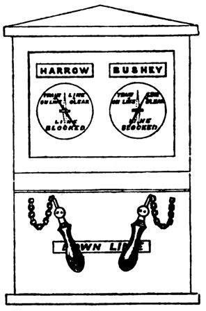
The criminal court case that followed was provided with a detailed description of the signal telegraph apparatus on the double-tracked North Kent railway in 1857: the dial had two compartments, in each of the compartments were two indicators, one bearing the words 'Stop all down' and 'Clear all down', and the other 'Stop all up' and 'Clear all up'. Over the instrument was placed on one side a gong for the down trains and on the other a bell for up trains, by the striking of which the attention of the signalman was attracted. The needle on the dial indicated that a train was about to pass up or down from one of the stations on either side. On receiving this the signalman returned an indication to the station from which the message had come, notifying that the line was 'clear' or 'stopped', and turned the line-side semaphore as necessary. The court's opinion on Tyer's arrangement was that "Nothing can be more satisfactory than this".In 1859 Tyer was working as electrical engineer for the London District Telegraph Company, promoted by the same individuals that launched the Signals company.
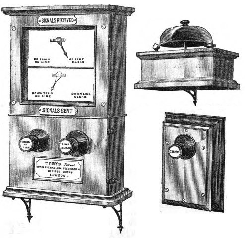
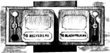
Tyer's Patent Train Signalling Telegraph 1868
with separate "gong" for messaging
This set is for working a single line of railway
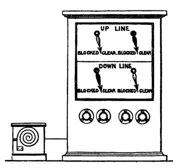
By 1862 he had established Tyer & Company to make and market "Tyer's train signalling telegraph", a much more basic manually-worked apparatus which used a single, two-position pointer for each line, derived in appearance from the familiar single-needle apparatus, but differing in stopping to the right or left until moved back when the situation changed.
The instrument in the hands of the signalman managing two lines of railway, 'Up' and 'Down', had a rectangular dial with four pointers upon it; two for incoming trains, coloured red, and for out-going trains, coloured black, on the 'Up' rails, with two similar on the 'Down' rails, so controlling four blocks in all. There were also instruments with two pointers, one red and one black, for single lines of rail. These pointers were worked either left for 'Clear' or right for 'Blocked' by four push-pull stops, called by Tyer "pistons", at the base of the dial. It sounded a Gong for up trains and a Bell for down trains worked by the stops for train code and attention signalling; with beats 1 - acknowledge, 2 - passenger train, 3 - goods train, 4 - express or light engine, 5 - obstruction, 6 - testing the gong or bell. Edward Tyer's system was continuously developed and altered over the rest of the century to become, apart from variations of the old single-needle telegraph, the most popular railway signal system.
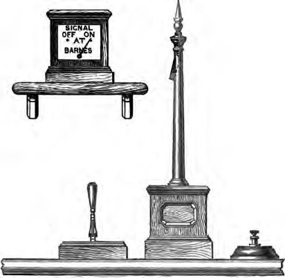
C V Walker's Miniature Semaphore 1854
Above - Message bell over a Receiver;
Below - two rotating Senders
The indicating components coloured red and white
d.] C V Walker's Miniature Semaphore Signal Telegraph
Charles Vincent Walker had introduced a bell telegraph between signal
boxes in January 1852 and that acoustic mechanism saw wide use on the
South Eastern Railway. It was the first generally adopted system of
electrical train control in Britain. In 1863 he had 330 bells in
operation, in pairs and with intermediate bells, each worked by a
so-called ringing-key, commonly termed a "pecker". Eighty-four of these
had automatic indexes to count the strikes, as up to twelve beats were
required for some signals! The bells, of traditional shape, were four
or five inches "across the mouth". Each bell set cost on average £4 6s
6d. The whole signal system had cost £3,650 in all, for bells,
ringing-keys, indexes, wires and batteries. They were worked by station
masters and ordinary signalmen.
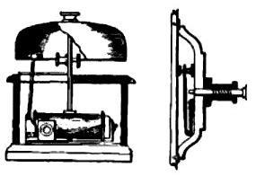
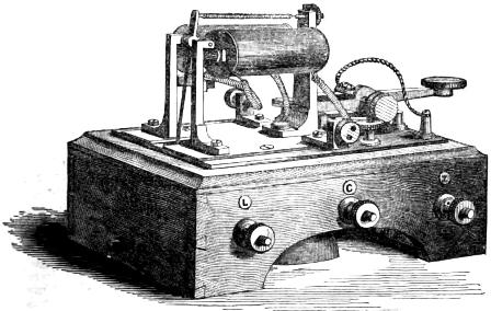
C V Walker's Bell 1852
Worked by galvanic batteries, left is the large bell on a rod,
the electro-magnet and striker in a case beneath,
right is the simple wall-mounted "ringing-key"
Walker's bells worked two codes of beats, one for train safety, one for simple station to station messages. In the General Code, for train safety, one beat signalled 'Up Train Out', two beats 'Down Train Out', three beats 'Train In', five beats 'Line Blocked' and six beats 'Unblock Line'. It was an absolute rule that every bell signal had to be repeated back to the sender.
By the mid-1850s Walker had added a visual component. This used an instrument with symbolic miniature railway semaphores on its dial face for each line of rails in each signal station operated by rotating keys. Each had two arms, one red and one white, worked up and down by electro-magnets. The Red arm indicated the state of the inward line, from a distant station; the White arm, the line for the outward line, from the home station. There was also a Bell. When the semaphore was up the line was 'Blocked' or occupied. When the semaphore arm was down the line was 'Clear'. The Bell attracted the signalman's attention and gave messages by a code of simple acoustic beats. It required just one wire without a constant current to function.The miniature semaphore was used so that those in charge of the out-door signals and points were warned by the same signals in the telegraph instrument signals with which every railway station-master, pointsman or porter was familiar.
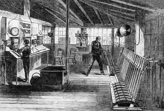
One of the South Eastern Railway Company's Signal Boxes
at London Bridge 1866
This very large terminus required complex control mechanisms.
In the centre background are a pair of Walker's miniature semaphore
telegraphs, to the left are two of Tyer's train signalling telegraphs,
to the right are the semaphore signal lever frames
e.] W H Preece's Miniature Semaphore Signal Telegraph
Designed by William Henry Preece this telegraph also used a miniature railway semaphore, but required two instruments and a separate electric bell for each line of rail. It actually took the form of wooden model semaphore signals on twelve inch tall posts operated by small vertical lever-switches. This system was complex, necessitating four instruments for two lines of rail each with three circuits using a constant current, the latter justified by the additional fail-safe factor in multiple wires. It was used by the London & South-Western Railway from 1863.
Edward Tyer was to point out that this was essentially a copy, and an unnecessary mechanical elaboration, of C V Walker's Electric Semaphore signal dating from 1854, exhibited at the Paris Exhibition of 1855.
Preece's reputation was further damaged by an accident on the South-Western railway at Egham on June 7, 1864 which killed seven people. It occurred on the line to the fashionable Ascot Races, and only narrowly missed involving the train carrying the Prince and Princess of Wales. The government's incident report said that the signalling system on the London & South-Western Railway was "most dangerous", as it relied entirely on a time interval between trains rather than the telegraph block.It must be said that much of this chapter is based on W H Preece's presentation to the Institution of Civil Engineers on his system in comparison with that of others in 1863, and the vitriolic responses he received from the railway signal engineers there present.
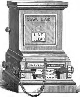
f.] Charles Spagnoletti's Disc Signal Telegraph
To make signalling as clear as possible this apparatus used a red and white coloured rotating disc on a green faced dial, with a red key and a white key. Two instruments were needed; one for 'Up' and one for 'Down' rails. Pressing the red key caused the red-half of the disc to appear on both the home and distant stations, the key could be locked down by a cross-pin. This indicated line 'Blocked'. Pressing the white key caused the white-half of the disc to rotate into view, showing line 'Clear'. Like all other railway signal telegraphs this had a Bell to attract attention and sound a code for the type of traffic; it was either a separate instrument with its own key, or built into the disc instrument and worked by either of the colour keys. This was introduced in 1863 on the intensely-worked Metropolitan Railway, the first underground line, and was eventually adopted by the Great Western Railway, for whom Spagnoletti worked, and its associated companies in the west of England, slowly from 1864.
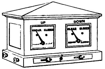
Bartholomew's Railway Signal Telegraph 1855
Essentially two single-needle telegraphs, worked by two
left-right sliding levers in the base
g.] E G Bartholomew's Railway Signal Telegraph
In addition Eugene George Bartholomew
introduced his own railway signalling system on to the London, Brighton
& South-Coast Railway in 1855, where he was superintendent of
telegraphs. This adapted the single-needle telegraph to give a
permanent indication by weighting the index so that it remained on
either the line 'Clear' or 'Closed' side of the dial. It also had a
bell alarum to attract attention, the 'down' line bell having one tone,
the 'up' line another, and to signal simple messages.
Rudall's Railway Bell Signal 1863
f.] Francis Rudall's Railway BellThe newly-appointed Telegraph Superintendant of the London, Chatham & Dover Railway, Francis Rudall, introduced electric blocking on the entire system in 1863. This was initiated by a fatal accident at the Chatham tunnel on July 9, 1862. Rudall improved the common single needle telegraph by having the signalman insert a pin either side of the needle to retain it in the 'Line Blocked' or 'Line Clear' side until the appropriate train had passed.
In addition Rudall improved upon C V Walker's railway bells by producing a unitary version, with the electro-magnetic striker and a tapper above a hemi- spherical bell contained in the base casing. It was able to work from between three miles up to twelve on a few cells with ease. The Rudall bell signal code was more elaborate than Walker's: one beat, stop all out train up; two beats, stop all out trains down; three beats, allow all trains in (station clear); four beats, special train; five beats, danger, stop all; six beats, all clear; seven beats, message on telegraph; and eight beats, testing circuit. All beats had to be repeated back.
Francis or Frank Rudall was the son of a celebrated flute maker and had risen in the service of the Electric Telegraph Company to become District Superintendant for north-west England in Liverpool before joining the Chatham railway in 1862.
Railway Telegraphs
As well as signal telegraphy, the railway
companies in Britain and Ireland worked their own internal telegraphs for
messaging as well as for train control. Circuits were set aside for railway use
with single-needle apparatus, whether Cooke & Wheatstone’s or Highton’s, in
the telegraph companies’ public wires alongside the rails, between passengers
stations, goods offices and workshops, as well as those in signal-boxes. These
were leased of the telegraph company as part of the wayleave agreement; who
undertook the maintenance of line and equipment. Messages, which reached around
300,000 a year for each of the largest companies such as the London &
North-Western, the South Eastern and the Lancashire & Yorkshire by 1867,
were entirely related to railway business, reporting incidents and weather,
organising rolling stock and traffic flows, and so forth; there was no intercommunication.
There was, and remains, remarkable ignorance
about the extent and importance of the railway companies’ internal messaging circuits.
The railway telegraphs were effectively parallel private networks to those used
by the public and of equal line length and traffic. However, no collective
figures relating to line or wire mileage worked by the railway companies were
published. On the appropriation by the Post Office in 1870 these circuits were
simply handed over to the railways as part of the price for not opposing the
state take-over. The railways then had to create their own Telegraph
Departments to take over the construction, maintenance and operating functions
previously undertaken by the telegraph companies. A large number of telegraph
company managers and clerks chose to join their existing co-workers on railways
rather than be absorbed into the Post Office regime.
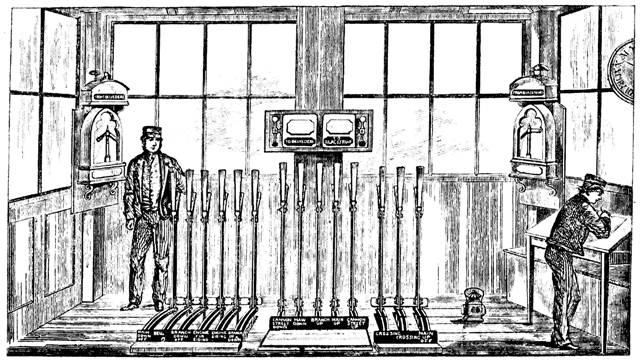
A Signal Box on the South-Eastern Railway in 1865
C V Walker's railway signal telegraph, up and down line senders in the centre, with
"miniature semaphore " receivers and alarms to either side.
Saxby & Farmer lever frames work the semaphores
Telegraph, from the Greek “tele”, distant, and “graphos”, writing